>> The Challenge:
It is extremely rare that the size of a part happens to conveniently fit the size of paper that we have available for printing. It therefore becomes necessary to scale things up or down as appropriate to suit.
>> The Reality:
You don’t want to draw the objects to scale for at least four reasons:
- First, it would involve calculating the scaled value of every single size and location dimension.
- Second, dimensions would return the scaled value and would all have to be over-written manually.
- Third, it could get very messy when you try to build an assembly by INSERTing or XREFing part files that are at different scales.
- Fourth, it is becoming more and more common for CAD data to be utilized for production processes such as CNC machining or flame cutting. If your parts aren’t drawn to scale, then the physical parts will be wrong.
>> The Solution:
Always draw everything full size. No matter if you are drawing an electronic microchip or a super tanker, always draw full size because we can tell the software to scale things up or down to suit the paper when we print.
Oops, this causes another problem. The printing process scales everything up or down, including text, dimensioning, hatch patterns, and non-continuous line types. For example, text notes and the numeric portion of dimensions are usually 1/8” (0.125) tall. If you apply 0.125” text to a drawing of a larger part and then print it at a 1:10 scale, the text will end up 0.0125” tall, which is a little difficult for old guys like me to read. Conversely, if you apply 1/8” text to the drawing of a watch gear, then it will totally overwhelm the part.
Fortunately, there are two possible solutions to this problem. Each solution has its advantages and disadvantages, as well as its corresponding supporters and opponents.
Let’s start with the older solution first, wherein all text and dimensions are placed in model space. Early CAD systems didn’t have paper space layouts, so this is the way we had to do it. We’ll cover this method because there are millions of older drawings out there that were created using this method. We’ll use the example of a larger part that will be scaled down to print.
Assuming that text and dimensions are placed in model space, the problem is that the text gets too small to read when its size gets scaled down along with everything else at print time.

Figure 1: Text and dimensions disappear when a large object is printed to scale.
The solution is simple; just make the text too big to begin with. Normally, two wrongs do not make a right (it usually takes three or four) but in this case they do. If you make the text 1.25” tall when you place it, then it will shrink to 0.125” when printed.

Figure 2: …but everything comes out right if we make the text and dimension larger.
That’s all there is to it. Text height is simply the desired height, usually 0.125”, multiplied by the inverse of the printing scale. A little later I’ll give you a simple chart of standard scale factors to help get you going.

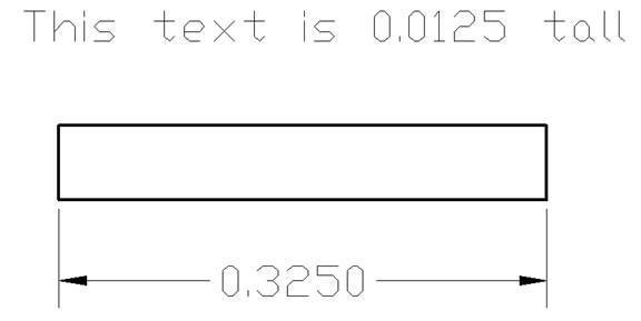
Figure 3: It works the other way for small objects printed larger…

Figure 4: …text and dimensions must be made smaller initially to print correctly.
Before we move on, let’s look at the easy way of producing text of a desired size. As you probably know, every time you use the TEXT or DTEXT commands, they start by asking you for the text height, with a default value of 0.200 tall. MTEXT doesn’t ask, but makes everything 0.200 unless you invoke its Height option. A real nuisance, right?
There are two simple solutions to this. The first is to invoke the TEXTSIZE command and change its value from the default 0.200 to the desired value. In the case of our 1:10 drawing it would be 1.25. Now, TEXT and DTEXT will offer and MTEXT will use 1.25 as the default.
The better solution is to invoke the STYLE command, or invoke the Text Styles option of the DWGeditor Explorer (EXPFONTS). In either case, a bit of looking around will reveal that the text height is specified as 0 (zero), which seems to be a strange value. Simply change it to the desired size and now not only will all text be the specified size but you will no longer get that annoying prompt each time asking you for a size.
Sizing Things Up:
Now we come to dimensioning.
Let’s start with the easiest one. As indicated for text, the PRINT command scales everything including text height, arrowhead size, extension line gap, and extension line overshoot. There are system variables that control all of these values, but the good news is that the DIMSCALE setting is an overall factor that is applied to all the others. It is thus only necessary to set the DIMSCALE to the inverse of the print scale and everything will adjust accordingly.
The annoying thing here is that the default size for the text component of a dimension is 0.180 as opposed to the default 0.200 for text. There is a long, complex historical reason for this that involves licensing rights, but we won’t go into that now.
The bottom line is that the DIMTXT setting changes this, but a little care must be exercised here. This value only applies if the text style used by the dimension style has a size of 0 (zero). However if the text style used by the dimension style has a value greater than zero, then that value is used instead. Oops. We want to change the general text height to suit our print scale, which will mess up our dimension text.
There is a very simple solution. Create a second text style. One has the desired fixed height for general text use, while the other has a height of 0 (zero) and is used for dimensions. Now set DIMTXT to the correct print height (usually 0.125), and all is right with the world.
Don’t Count Your Hatches…
Hatch patterns have the same scale issues as text and dimensions. If you hatch a large area and then plot it at a reducing scale, then the hatch elements will be too close together, while a very small area may be smaller than the distance between hatch elements.
As before, the solution is simple. When you create a hatched area, set its scale factor to the inverse of the final print scale as we did for text and dimensions.
The next adjustment needed to correct for print scaling involves non-continuous line types. Once again the lengths of dashes and spaces will be scaled when printing. LTSCALE globally sets the scale factor for all non-continuous line types. Any guesses as to what it should be set to? Right! The inverse of the print scale. Gosh, what a surprise.
The final item to be considered is borders and title blocks. They will also be scaled down or up by the printing process, and so they will have to be made larger or smaller by our now well-known suitable factor.
>> Notes to You:
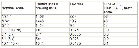
As promised, here is a quick chart to help you get started with common scale factors.

Make sure you select the intended print scale before applying text, dimensions, or hatching. LTSCALE is the only factor that applies globally and retroactively to the entire drawing. Changes to all other size factors only apply to new entities created after the factors were changed.
To save time, decide on a set of standard scale factors for your office and then create a set of template files that incorporate suitable scale factors. Now you can easily start a 1:1 drawing, or a ¼” = 1’ drawing, or a 5:1 drawing, and so on.
The bottom line is that if you zoom in or out so that the screen shows the intended print area and everything looks right, then it probably is.
Be sure to come back next time when we explore how to put text and dimensions in paper space layouts, and the relative merits of putting them there versus model space.
>> Command review:
- Print
- Keyboard: Print
- Menu: File > Print
- Toolbar: Standard > Print
- Alias: Plot
- Single-line text
- Keyboard: Text
- Alias: TX
- Paragraph text
- Keyboard: DText
- Menu: Insert > Text
- Toolbar: Draw 2D > Text
- Alias: DT
- Multiline text
- Keyboard: MText
- Menu: Insert > Multiline Text
- Toolbar: Draw 2D > Multiline Text
- Alias: MT
- Text size:
- Keyboard: TextSize
- Text settings:
- Keyboard: Style, ExpFonts
- Menu: Settings > Explore text styles
- Dimensioning:
- Keyboard: DimLinear, DimAligned, DimAngular, DimDiameter, DimRadius, DimLeader
- Menu: Insert > Dimensions > …
- Toolbar: Dimensioning > …
- Aliases: Linear, Aligned, Angular, Diameter, Radius, Leader
- Dimension Settings:
- Keyboard: SetDim
- Menu: Insert > Dimensions > …
- Toolbar: Dimensioning > …
- Dimension text size:
- Keyboard: DimTxt
- Non-Continuous Lines:
- Keyboard: LTScale
- Alias: LTS

