>> The Challenge:
You have designed a new machine, and are now working on the 2D shop layout for its installation. You need to run essential service lines and hoses to it, such as compressed air, cooling water, power, and so on. You want the lines to be repeatedly tagged with a text label so they are easy to follow.
>> The Reality:
Although DWGeditor® comes with a large library of different non-continuous line types, they don’t contain the labels you need. Line type definitions are contained in an external file that can be edited to add the ones you want, but this can be a lengthy process and is not fully documented.
>> The Solution:
Custom-labelled lines can easily be created by merging a few existing commands along with a previous tip entitled “Who is That Masked Object?”. In it we explored how to use the 3Dface command to mask out portions of a drawing. This time we are going to see a specific application for this technique as used to quickly create custom text-labelled line types.
Simply follow these easy steps:
- Use the Text command to create a suitable word or string of text. Use the following options:
- Alignment: Middle
- Start point: 0,0,1 (note the Z-axis value of 1)
- Height: <as appropriate for your drawing scale>
- Rotation angle: 0 (zero)
- Text: <as appropriate>
- Use the 3DFace command to create a rectangle around the text.
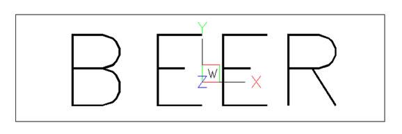
Figure 1: Create a text object and a 3D face
- Double-click on the 3D face in order to bring up the Entity Properties dialog box:
- Change the four Z-axis values to 0.5.
- Check the four “Invisible Edges” boxes.
- Click OK
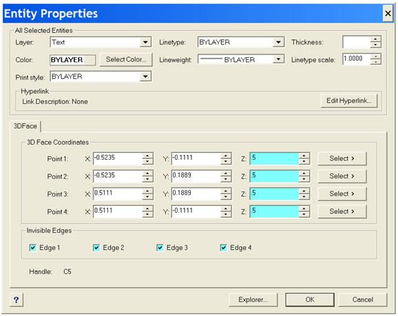
Figure 2: change the z-axis and the edge visibility of the 3D face
- Start the Block command:
- Block name: <a logical choice would be to use the contents of the text string that you created earlier>
- Insertion point: 0,0,0 (note the Z-axis value of zero)
- Select objects:
- Select the text item
- Enter the letter L. (This selects the “last” item created, which is the 3D face, which cannot otherwise be selected because it is invisible).
- Draw a spline curve.
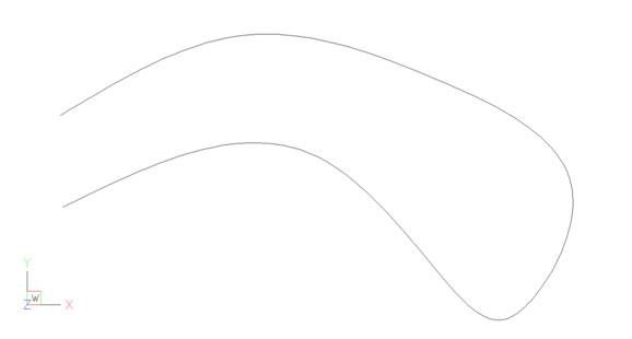
Figure 3: draw a spline curve
- Start the Measure command. Surprisingly, this command doesn’t measure the length of an object. Instead, it repeatedly places markers along the object spaced a specified distance apart. By default the markers are Point objects, but we can substitute a block definition instead.
- Select entity to measure: <pick the spline created in step 5>
- Block/segment length: <Enter the letter B>
- Block to insert: <enter the name of your label block>
- Align blocks with entity: Y
- Segment length: <pick or specify a distance about five times greater than the width of your label block>
Your label block repeats itself along the selected entity, and the text always stays aligned with the object and the right way up. More on this later.
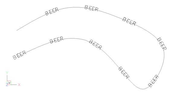
Figure 4: use the Block option of the Measure command to repeat the labels along the spline
- Run the Hide command. Presto! You now have a non-continuous line that is repeatedly labelled with the desired text as a series of block insertions. It was not necessary to mess with the line type definition file at all, and you can send the file to other users without worrying about “custom” line definitions.
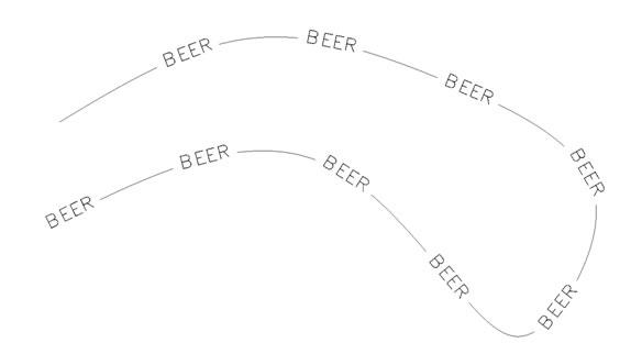
Figure 5: the Hide command produces the final result.
>> Notes to you:
Ah, but there is no free lunch (unless maybe you work for the government). This technique is really a bit of a cheat in that it doesn’t actually create a line type definition. You will have to use the Measure command separately on each object that you want to label. In addition, the blocks are not associative to the object so that if you need to change the size or location of the object then you will need to manually move or delete the tags and re-apply them to the modified object. For this reason, it is an excellent idea to put the tag blocks on a unique layer so that you can freeze all other layers in order to simplify selection of the tags you want to delete.
The basic secret that makes this trick work is the fact that the text is “above” the 3DFace, which in turn is “above” the labelled object. The Hide command will need to be run just before you plot the drawing. Regen makes the hiding go away, and so the underlying object will become visible through the text.
This technique will work on lines, polylines (including curve-fit ones), splines, arcs, circles. and ellipses.
Block placement starts at the end closest to where the entity was selected and proceeds from there. Splines and ellipses try to keep the text the right way up, but the text alignment of the other object types depends on which end was closer when you picked the entity. Note the two horizontal lines, for example.
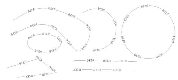
Figure 6: this technique produces slightly different results on different entity types
Label blocks can include other symbols as well as text, such as flow direction arrows.
If you omit step 3b then each tag will be outlined by a rectangle.
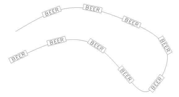
Figure 7: Leave the edges visible to get boxes around the labels
Good Luck!
>> Command Review:
- Text
Keyboard: Text
Alias: T, TX
Menu: Insert > Text
Toolbar: Text > Text
- 3Dface
Keyboard: Face
Alias: 3Dface
- Properties
Keyboard: EntProp
Menu: Modify > Properties
Toolbar: Modify > Properties
- Hide
Keyboard: Hide

